
4-Axis CNC Machining in China: How to Prove the Machine Can Make Your Part
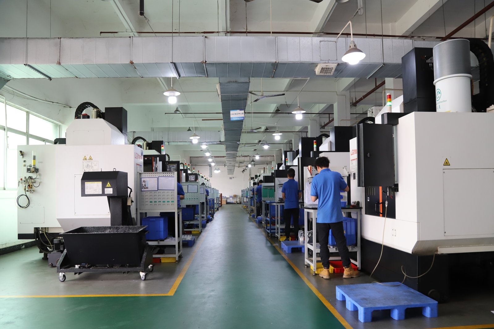
Every supplier can say it runs 4-axis machining; the question a verification-driven buyer asks is different — what evidence proves the machine, the program, and the process can make this specific part? Four-axis capability hides in the details: whether the fourth axis is continuous or indexing, whether the rotary table holds its position under load, whether the program was written and verified for the actual geometry, and whether the batch stays inside tolerance after the first article. This guide turns those details into evidence: which features on your drawing justify a fourth axis, what the process record should show, how to design a test piece that actually proves the machine, and what to require in the purchase order so the proof arrives with the parts.
Which features on your drawing are the evidence that you need a fourth axis?
Before asking a supplier to prove 4-axis capability, establish what the drawing demands — the features themselves are the first piece of evidence, because they define what the machine must be able to do. Four feature families justify a rotary axis, and each one implies a different capability claim:
- Features on multiple faces that must relate to each other. A hole on one face that must clock precisely to a slot on an adjacent face — the relationship crosses a setup boundary, so the claim is that one clamping on a rotary axis produces the relationship in a single coordinate system.
- Patterns around a common axis. Bolt circles, cross-holes at intervals around a cylinder, slots spaced around a hub — the claim is that each position is generated from the part's true axis by the machine's rotation, not rebuilt by a series of manual setups.
- Features at controlled angles to a datum. A drilled hole at 30 degrees, a machined pad at an angle — the claim is that the angle comes from the machine's indexed rotation, which is repeatable and verifiable, rather than from an angled fixture whose accuracy is a shop-floor judgment.
- Helical or wrap-around geometry. A groove that spirals around a diameter, a cam profile, a feature that must be cut while the part rotates — the claim here is continuous four-axis motion, which is a different machine and a different program from indexed work, and the drawing should say so explicitly.
Mark these features on the drawing or in the RFQ notes. The list is the verification contract: it tells the supplier which capability claims the order depends on, and it tells you which evidence to demand. A drawing with none of these features does not need a fourth axis, and if the RFQ still says 4-axis, the first question to ask is why.
What should the process record show before a 4-axis job runs?
Once the features justify the axis, the next evidence is the process record — how the supplier intends to make the features, written down before the job runs. A 4-axis process record that can be audited shows four things:
- The machining strategy per feature family. For each indexed face: the rotation angle, the datum the angle is referenced from, and the operations run in that orientation. For continuous features: the program strategy and the axis coordination it depends on. The record should make clear which features are indexed and which — if any — require continuous motion, because the two make different demands on machine and program.
- The workholding plan. How the part is held for rotation — the fixture, the clamping points, and how the part's datum features are established in the rotary setup. On 4-axis work the fixture carries half the accuracy, so the plan is evidence of how the cross-face relationships will be held, not an administrative detail.
- The program and its verification. The CAM program and post-processor for the machine, plus evidence the toolpaths were verified — simulation where the geometry is complex, and a dry run or careful first-article protocol where the risk is concentrated. A process record that includes program verification is the difference between a planned job and an experiment.
- The inspection points. Which features are measured, on what instrument, and at what stage — first article full dimensional check, then the cross-face relationships that the rotary axis exists to produce. The inspection plan defines what "done correctly" means before the job starts.
A supplier that produces this record before cutting is running 4-axis work as a process. One that cannot describe the strategy, fixture, program verification, and inspection points until after the parts exist is asking you to fund its learning curve.
How do you design a test piece that actually proves the machine?
A test piece is the most direct evidence a 4-axis supplier can give, and its value depends entirely on how it is designed. A test part that merely reproduces what a 3-axis machine could do proves nothing about the fourth axis. A meaningful test piece exercises the capability claims your parts depend on:
- Put features on at least two faces with a relationship between them. A bore on one face and a counterbore or slot on the adjacent face, with a position tolerance between them — this tests whether one rotary setup holds cross-face relationships in a single coordinate system.
- Include a circular pattern around an axis. Holes at intervals around a cylinder, toleranced to a common centerline — this tests whether the rotary axis positions each feature from the part's true axis with repeatable accuracy.
- Add one angled feature. A hole or face at a non-orthogonal angle to a datum — this tests the indexing accuracy at an angle that no hand fixture can set casually.
- If your part has continuous geometry, the test piece must too. For helical or cam features, the test should include the same class of continuous motion — an indexed-only test piece says nothing about continuous capability.
- Measure the relationships, not just the sizes. The acceptance report should show the cross-face position and angular relationships measured on a CMM — the features that only a rotary setup can deliver. Sizes alone would pass on a 3-axis machine; the relationships are what the fourth axis is for.
A test piece built on this logic turns "we have 4-axis machines" into measured evidence about the capabilities your drawing needs. The cost of the test piece is small; the information it returns — whether this supplier's fourth axis actually delivers cross-feature accuracy — is the information the production order depends on. Two rules keep the test honest. First, the acceptance criteria are written before the test runs: the position tolerance the cross-face features must meet, the angular deviation the indexing must hold, the pattern error the rotation must stay inside. A test piece without pre-agreed criteria produces a report that can be interpreted generously after the fact. Second, the test piece is machined in the same class of setup as production — same machine type, same fixture philosophy, same program style — because a test cut on a showcase machine with a hand-built fixture proves nothing about the setup that will make your parts.
Which machine and rotary-table evidence matters before you order?
Beyond the test piece, the machine itself carries evidence a buyer can review without cutting any metal:
- The rotary table configuration and its specification. What kind of table — trunnion, tilting, or a plain rotary axis — and what positioning accuracy and repeatability the builder specifies. The specification sets the ceiling on what the machine can deliver, and the ceiling should be an order of magnitude inside your tolerances, not merely close to them.
- Calibration and maintenance records for the rotary axis. A rotary table drifts with use — backlash develops, the axis loses its compensation. The supplier's calibration schedule and its most recent records show whether the machine on the floor is the machine on the spec sheet. No record, no claim: an uncalibrated rotary axis is a source of error the supplier has chosen not to measure.
- The machine's geometry verification. Linear axes and the rotary axis are verified periodically with laser or ballbar checks, which catch the wear and drift that accumulate between rebuilds. The records of these checks are the machine's health history, and they predict your part's accuracy better than the machine's purchase date.
- Inspection reports from comparable 4-axis work. A report from a real job with cross-face features — measured values, not stamps — shows the machine and its programmers delivering the kind of relationships your drawing demands. If the only evidence is the machine list, the capability statement is still unproven.
The buyer-side discipline: a 4-axis claim is a stack of evidence — machine specification, calibration records, geometry checks, and comparable inspection reports — and the stack is only as strong as its weakest documented link. Ask for the stack, not the slogan.
How is the batch proven, not just the first article?
The first article proves the setup can make one correct part. Production proves the setup keeps making them, and the batch evidence is what actually protects a 4-axis order:
- Key cross-face features are the ones charted. The features the rotary axis exists to produce — the relationships between faces, the pattern positions, the angled features — are exactly the ones that should appear in the process capability data. A Cpk of 1.33 or better on these characteristics shows the rotary process is stable, not just the first article.
- Sampling is planned, not improvised. The inspection frequency — how often the cross-face features are measured through the run — should be agreed in advance and stated in the process record. Frequency that changes when problems appear is reaction, not control.
- Rotary setup consistency is checked across the run. If the job comes off the machine and goes back on — for a second operation, for example — the datum re-establishment is a fresh source of error, and the record should show it was controlled and verified, not assumed.
- Every part or lot traces to the setup that made it. The batch record ties parts to the machine, the program revision, the fixture, and the inspection results, so a future question about any part can be answered from the record rather than reconstructed from memory.
A 4-axis order is not proven by one impressive first article; it is proven by a run whose key relationships stay inside tolerance with data behind them. The batch evidence — capability indices, sampling records, and traceability — is what turns a demonstration into a process. The record also closes the loop: capability data that shows drift approaching the tolerance limit is a signal to tighten the process — adjust the fixture, refresh the tooling strategy, re-check the rotary setup — before parts leave the band, not after. A supplier that reads its own batch data and acts on it is running axis work as a controlled process; one that produces the report and nothing else is documenting, not controlling.
What should a 4-axis purchase order require as evidence?
The evidence chain is only as strong as the contract that demands it. A 4-axis PO carries requirements that turn each link of the proof into a deliverable:
- The axis features, identified. The drawing or PO notes which features justify the fourth axis and whether any require continuous motion, so the capability claim is defined before the price is agreed.
- The process record, delivered before production. Strategy per feature, workholding plan, program verification, and inspection points — reviewed before the run, not after.
- Test-piece acceptance where the order justifies it. For a first-time supplier or a new class of geometry, a designed test piece with CMM-measured relationships, accepted before production tooling is committed.
- Machine evidence on request. Rotary table specification, calibration records, and geometry verification history — available on request as part of the capability review.
- Batch data with the shipment. Capability data on the key cross-face features, the sampling record, and the lot-to-setup traceability — the proof that the run, not just the sample, stayed inside tolerance.
A supplier that prices these requirements as a normal part of 4-axis work is selling a process. One that treats them as unreasonable demands is selling a machine it has not yet learned to prove, and on axis work, the proof is the product.
Frequently Asked Questions
How do I know whether my part actually needs a fourth axis?
Look at the drawing for three feature families: features on multiple faces that must relate to each other within a tight tolerance, patterns positioned around a common axis, and features at controlled angles to a datum. Any of these justifies a rotary setup; helical or wrap-around geometry additionally demands continuous four-axis motion. If none is present, the part is a 3-axis job, and a 4-axis quote is overcapacity.
What is the difference between 4-axis and 3+1-axis machining?
The practical difference is in the motion, and it shows up in the program. Indexed work — often called 3+1 — rotates the part to a fixed angle, holds it there, and machines that face with ordinary 3-axis toolpaths, repeating for each orientation; most multi-face and patterned parts are made this way. Continuous 4-axis work coordinates the rotary axis with the other three during the cut itself, which is what helical grooves, cam lobes, and wrap-around profiles require. The drawing's features decide which one applies, and the process record should show which one the program actually uses.
How can a test piece prove a supplier's 4-axis capability?
If it is designed to exercise the capability claims: features on multiple faces with position tolerances between them, a circular pattern toleranced to a common centerline, and an angled feature — measured on a CMM for the relationships, not just the sizes. A test piece that only reproduces 3-axis work proves nothing about the fourth axis; one that demands cross-face accuracy turns the machine claim into measured evidence.
Does 4-axis machining hold tighter tolerances than 3-axis?
On any one feature, no: a well-run 3-axis machine and a well-run 4-axis machine hold the same ±0.003 mm class of tolerance on a flat face, because the axis count does not change how a single cut holds size. What the fourth axis changes is where error would otherwise enter — between the setups that machine different faces. Cutting a relationship across two faces in one rotary setup removes the re-clamping error that would otherwise stack into that relationship, so the tolerance that improves is the one your drawing places between features on different faces. That distinction decides whether the axis is worth its cost: it buys cross-face accuracy, and it does not buy tighter numbers on any single surface.
What machine evidence should I ask for before ordering 4-axis work?
Four items: the rotary table's specification (positioning accuracy and repeatability), its calibration schedule and most recent records, the machine's geometry verification history (laser or ballbar checks), and inspection reports from comparable 4-axis jobs with measured cross-face values. The stack of evidence, not the machine list, is what proves the claim.
What is the minimum order quantity for 4-axis machined parts?
One piece, which makes a single-part order the natural vehicle for the proof: the test geometry, the process record, and the CMM-measured relationships can all be exercised on one part before a production batch is committed to the same setup.